In my previous post, I verified a way to install wireless interfaces with different physical properties on ns2 nodes. However, in that scenario, we assumed that all nodes have only one interface.
Recently, I have to work on scenarios which require multiple wireless interfaces on one node. Furthermore, it is possible that those interfaces on the same node may have different physical properties (e.g., different Rx and CS thresholds). I have accomplished install more than one wireless interfaces on one node, using Ramon's method. However, the previous approach of changing configurations of individual interface does not work any more. This is because it changes the default configurations for all wireless interface before the node is created, and ns2 set the properties of all its interfaces using those default values when it adds interfaces onto itself.
To solve these problem, we need to way to manipulate any individual interface and change its configurations after the node is created. The following gives the solution:
1. At the beginning of your ns2 script, create a new function:
Node/MobileNode instproc getPhy {ifa } {
$self instvar netif_
return $netif_($ifa)
}
where ifa is the index of the interface.
2. After node is created, we can use this function to get the interface object.
3. Because ns2 already binds some member variables of class WirelessPhy, we use the interface object obtained from step 2 to set those binded variables directly.
Following is a snippet from my script:
--------------------------------------------------------------------
$ns change-numifs 1
$ns add-channel 0 $chan_(0)
#$ns add-channel 1 $chan_(1)
set node_(0) [$ns node]
$node_(0) set X_ 0.0
$node_(0) set Y_ 0.0
$node_(0) set Z_ 0.0
set phy [$node_(0) getPhy 0]
$phy set RXThresh_ 1.08918e-9 ;#FreeSpace, 160m
$ns change-numifs 2
$ns add-channel 0 $chan_(0)
$ns add-channel 1 $chan_(1)
set node_(1) [$ns node]
$node_(1) set X_ 150.0
$node_(1) set Y_ 0.0
$node_(1) set Z_ 0.0
set phy [$node_(1) getPhy 0]
$phy set RXThresh_ 1.08918e-9 ;#FreeSpace, 160m
set phy [$node_(1) getPhy 1]
$phy set RXThresh_ 4.4613e-10 ;#250m
$ns change-numifs 1
$ns add-channel 0 $chan_(1)
#$ns add-channel 1 $chan_(1)
set node_(2) [$ns node]
$node_(2) set X_ 350.0
$node_(2) set Y_ 0.0
$node_(2) set Z_ 0.0
set phy [$node_(2) getPhy 0]
$phy set RXThresh_ 4.4613e-10 ;#250m
--------------------------------------------------------------------
The first three lines specify that two interfaces will be installed on node 1. After node 1 is created, we got the second interface object through function getPhy, and changed its Rx threshold. Note that we did not change configurations for the 1st interface (indexed as 0) and it uses default values.
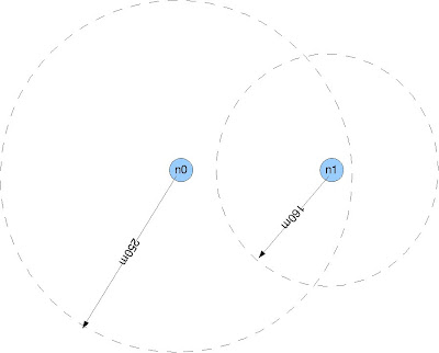
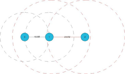
Now, we need to verify that this approach is working. We place three nodes in the testing topology. Node 0 installed one interface which connects to channel 0, the transmission range is 160m. Node 1 installed two interfaces: the first interface connects to channel 0 and it also has a 160m transmission range; the second interface connects to channel 1 and has 250m transmission range. Node 2 has only one interface, and it connects to channel 1 with transmission range of 250m. The default transmission range is set to 160m.
We set up a cbr flow from node 0 to node 2, and 100 packets will be sent. If all interface has the same default transmission range, the flow will not succeed.
Simulation result shows that the flow did success. Here is some statistics:
sentPkts: 100
receivedPkts: 100
droppedPkts: 0
firstSendTime: 1
lastRecvTime: 1.82209
pktSize: 512
avgThroughput: 498244
node 0 sent 100 packets.
node 2 received 100 packets.
We also increased the distance between node 0 and node 1 to 200m, and keep the distance between node 1 and node 2 as 200m, and did the experiment again. This time, no packet was delivered to node 2.
Recently, I have to work on scenarios which require multiple wireless interfaces on one node. Furthermore, it is possible that those interfaces on the same node may have different physical properties (e.g., different Rx and CS thresholds). I have accomplished install more than one wireless interfaces on one node, using Ramon's method. However, the previous approach of changing configurations of individual interface does not work any more. This is because it changes the default configurations for all wireless interface before the node is created, and ns2 set the properties of all its interfaces using those default values when it adds interfaces onto itself.
To solve these problem, we need to way to manipulate any individual interface and change its configurations after the node is created. The following gives the solution:
1. At the beginning of your ns2 script, create a new function:
Node/MobileNode instproc getPhy {ifa } {
$self instvar netif_
return $netif_($ifa)
}
where ifa is the index of the interface.
2. After node is created, we can use this function to get the interface object.
3. Because ns2 already binds some member variables of class WirelessPhy, we use the interface object obtained from step 2 to set those binded variables directly.
Following is a snippet from my script:
--------------------------------------------------------------------
$ns change-numifs 1
$ns add-channel 0 $chan_(0)
#$ns add-channel 1 $chan_(1)
set node_(0) [$ns node]
$node_(0) set X_ 0.0
$node_(0) set Y_ 0.0
$node_(0) set Z_ 0.0
set phy [$node_(0) getPhy 0]
$phy set RXThresh_ 1.08918e-9 ;#FreeSpace, 160m
$ns change-numifs 2
$ns add-channel 0 $chan_(0)
$ns add-channel 1 $chan_(1)
set node_(1) [$ns node]
$node_(1) set X_ 150.0
$node_(1) set Y_ 0.0
$node_(1) set Z_ 0.0
set phy [$node_(1) getPhy 0]
$phy set RXThresh_ 1.08918e-9 ;#FreeSpace, 160m
set phy [$node_(1) getPhy 1]
$phy set RXThresh_ 4.4613e-10 ;#250m
$ns change-numifs 1
$ns add-channel 0 $chan_(1)
#$ns add-channel 1 $chan_(1)
set node_(2) [$ns node]
$node_(2) set X_ 350.0
$node_(2) set Y_ 0.0
$node_(2) set Z_ 0.0
set phy [$node_(2) getPhy 0]
$phy set RXThresh_ 4.4613e-10 ;#250m
--------------------------------------------------------------------
The first three lines specify that two interfaces will be installed on node 1. After node 1 is created, we got the second interface object through function getPhy, and changed its Rx threshold. Note that we did not change configurations for the 1st interface (indexed as 0) and it uses default values.
Now, we need to verify that this approach is working. We place three nodes in the testing topology. Node 0 installed one interface which connects to channel 0, the transmission range is 160m. Node 1 installed two interfaces: the first interface connects to channel 0 and it also has a 160m transmission range; the second interface connects to channel 1 and has 250m transmission range. Node 2 has only one interface, and it connects to channel 1 with transmission range of 250m. The default transmission range is set to 160m.
We set up a cbr flow from node 0 to node 2, and 100 packets will be sent. If all interface has the same default transmission range, the flow will not succeed.
 |
| From public |
Simulation result shows that the flow did success. Here is some statistics:
sentPkts: 100
receivedPkts: 100
droppedPkts: 0
firstSendTime: 1
lastRecvTime: 1.82209
pktSize: 512
avgThroughput: 498244
node 0 sent 100 packets.
node 2 received 100 packets.
We also increased the distance between node 0 and node 1 to 200m, and keep the distance between node 1 and node 2 as 200m, and did the experiment again. This time, no packet was delivered to node 2.