From my discussions with Muhamad on ns2 mail list, he provided a solution to use different transmission ranges in one ns2 wireless simulation. To verify this solution, I created a simple scenario and a test script, and let ns2 run it. The results was good: I observed the effect of different transmission range.
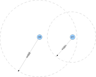
The scenario is as follows. Two wireless nodes n0 and n1 are placed into a flat area and have distance of 200m. Both nodes send packets with the same transmission power, but have different receiving range. I set n0's receiving range to 250m, and its carrier sensing range to 550m. n1's receiving range is 160m, and its carrier sensing range is 400m.
Both nodes try to send exactly one packet to the other using DSR. Because there is no bi-directional connection exist, the actual data connection could not be be established (DSR needs a bi-directional connection for route discovery). However, we can verify the difference of two transmission ranges by observing the reachability of DSR RREQ packets broadcast by each node.
The first connection starts at the 1st second, from n0 to n1. The second connection starts at the 5th second, from n1 to n0. By analyzing the trace file, I found that the all RREQ packets from n0 were not heard by n1. But all RREQ packets sent by n1 were successfully received by n0. This makes sense because n1's receiving ranges (160m) is samller than its distance to n0 (200m), thus it cannot heard any packet from n0. However, because n0's receiving range (250m) is bigger than the distance, it can hear RREQ from n1. n0 also sent out replies to n1, but n1 could not heard it.
The tcl script:
-----------------------------------
# n0 and n1 use the same transmission power.
# n0 has a receiving range of 250m, n1's receiving range is 160m.
# n0 and n1 are 200m away from each other.
# n1 cannot receive routing requests broadcast by n0;
# however, n0 can receive routing requests broadcast by n1.
# ==========================================================
#Definition
# ==========================================================
set opt(chan) Channel/WirelessChannel ;# channel type
set opt(prop) Propagation/FreeSpace ;# radio-propagation
set opt(ant) Antenna/OmniAntenna ;# Antenna type
set opt(ll) LL ;# Link layer type
set opt(ifq) CMUPriQueue ;# Interface queue
set opt(ifqlen) 100 ;# max packet in ifq
set opt(netif) Phy/WirelessPhy ;# network interface
set opt(mac) Mac/802_11 ;# MAC type
set opt(nn) 2 ;# number of mobilenodes
set opt(rp) DSR ;# routing protocol
set opt(x) 1000
set opt(y) 1000
set opt(seed) 0.0
set opt(stop) 10.0
# ==========================================================
# Initialize Global Variables
# ==========================================================
set ns [new Simulator]
$ns use-newtrace
set trace [open out.tr w]
$ns trace-all $trace
set namtrace [open out.nam w]
$ns namtrace-all-wireless $namtrace $opt(x) $opt(y)
# ==========================================================
# set up topography object
# ==========================================================
set topo [new Topography]
$topo load_flatgrid $opt(x) $opt(y)
# ==========================================================
# Create God --> General Operations Director
# ==========================================================
create-god $opt(nn)
# ==========================================================
# Create channel (koneksi wireless)
# ==========================================================
set chan_1 [new $opt(chan)]
# ==========================================================
# configure and create nodes
# ==========================================================
$ns node-config -addressType expanded \
-adhocRouting $opt(rp) \
-llType $opt(ll) \
-macType $opt(mac) \
-ifqType $opt(ifq) \
-ifqLen $opt(ifqlen) \
-antType $opt(ant) \
-propType $opt(prop) \
-phyType $opt(netif) \
-topoInstance $topo \
-agentTrace ON \
-routerTrace ON \
-macTrace OFF \
-movementTrace OFF \
-channel $chan_1
# ====================================================================
# create node 0, receiving range 250m, carrier sensing range 500m
# ====================================================================
Phy/WirelessPhy set CPThresh_ 10.0
Phy/WirelessPhy set CSThresh_ 9.21756e-11 ;#550m
Phy/WirelessPhy set RXThresh_ 4.4613e-10 ;#250m
Phy/WirelessPhy set bandwidth_ 512kb
Phy/WirelessPhy set Pt_ 0.2818
Phy/WirelessPhy set freq_ 2.4e+9
Phy/WirelessPhy set L_ 1.0
Antenna/OmniAntenna set X_ 0
Antenna/OmniAntenna set Y_ 0
Antenna/OmniAntenna set Z_ 0.25
Antenna/OmniAntenna set Gt_ 1
Antenna/OmniAntenna set Gr_ 1
set node_(0) [$ns node]
$node_(0) random-motion 0
$node_(0) set X_ 0.0
$node_(0) set Y_ 0.0
$node_(0) set Z_ 0.0
# ===================================================================
# create node 1, receiving range 160m, carrier sensing range 400m
# ===================================================================
Phy/WirelessPhy set CPThresh_ 10.0
Phy/WirelessPhy set CSThresh_ 1.74269e-10 ;#400m
Phy/WirelessPhy set RXThresh_ 1.08918e-9 ;#160m
Phy/WirelessPhy set bandwidth_ 512kb
Phy/WirelessPhy set Pt_ 0.2818
Phy/WirelessPhy set freq_ 2.4e+9
Phy/WirelessPhy set L_ 1.0
Antenna/OmniAntenna set X_ 0
Antenna/OmniAntenna set Y_ 0
Antenna/OmniAntenna set Z_ 0.25
Antenna/OmniAntenna set Gt_ 1
Antenna/OmniAntenna set Gr_ 1
set node_(1) [$ns node]
$node_(1) random-motion 0
$node_(1) set X_ 200.0
$node_(1) set Y_ 0.0
$node_(1) set Z_ 0.0
# UDP connections between from node_(0) to node_(1)
set udp_(0) [new Agent/UDP]
$ns attach-agent $node_(0) $udp_(0)
$udp_(0) set fid_ 1
set null_(0) [new Agent/Null]
$ns attach-agent $node_(1) $null_(0)
set cbr_(0) [new Application/Traffic/CBR]
$cbr_(0) set packetSize_ 512
$cbr_(0) set rate_ 200kb
$cbr_(0) set maxpkts_ 1
$cbr_(0) attach-agent $udp_(0)
$ns connect $udp_(0) $null_(0)
$ns at 1.0 "$cbr_(0) start"
set udp_(4) [new Agent/UDP]
$ns attach-agent $node_(1) $udp_(4)
$udp_(4) set fid_ 2
set null_(4) [new Agent/Null]
$ns attach-agent $node_(0) $null_(4)
set cbr_(4) [new Application/Traffic/CBR]
$cbr_(4) set packetSize_ 512
$cbr_(4) set rate_ 200kb
$cbr_(4) set maxpkts_ 1
$cbr_(4) attach-agent $udp_(4)
$ns connect $udp_(4) $null_(4)
$ns at 5.0 "$cbr_(4) start"
$ns at $opt(stop).0002 "puts \"ns EXITING...\" ; $ns halt"
$ns at $opt(stop).0001 "finish"
proc finish {} {
$ns flush-trace
close $tracefd
close $namtrace
exit 0
}
puts "Starting Simulation..."
$ns run
Powered by ScribeFire.