Tuesday, April 1, 2008

get a reference to node at MAC layer

The mac layer itself does not have a data or function member to return the node object. However, it has an reference to its physical interface, which can access the node object. My code to access node object in mac-802_11.cc is

((WirelessPhy*)netif_)->node();


Powered by ScribeFire.

get a reference to node at wireless physical layer

Both Class wirelessPhy and Phy provide a function to access its protected member node_, which refers to its node object. For example, if one wants to know the node id in the physical layer, use the following command:

node()->nodeid(), which returns an integer.


Powered by ScribeFire.

ns-2.33 added new mac models

Today, a new version of ns (2.33) has been announced. Several new 802.11 models has been added into this version, which is an exciting news. Here is a summary of these new models:

  • 802.11 infrastructure extensions:
Support AP, and inter-AP communications, and handoff. (http://ee.washington.edu/research/funlab/802_11/report_80211_IM.pdf)

  • 802.11 Ext
Mercedes-Benz R&D contributed to this model (I am surprised to know Mercededes-Benz is also interested in network simulation). Neat function structure design, more accurate SINR computation, physical layer tracing, Nakagami fading model. In short, it should be a better choice for general 802.11 simulation. The ns doc says "The model should be used as a replacement for the existing models". (http://dsn.tm.uni-karlsruhe.de/Overhaul_NS-2.php)

  • dei802.11 mr
Multirate 802.11 module. Users are now supposed to be able to use different transmission rates, modulation and coding schemes. There's no RxThresh and CSThresh in this model. The packet reception is determined by a pre-defined PER-SINR curve. Users with such curve will be happy to use this model. (http://www.dei.unipd.it/%7Ebaldo/nsmiracle-dei80211mr-howto.html).


Also, from version 2.33, ns2 supports dynamical library, which means users don't need to touch the core source of ns to implement their own models. Cheers!

The original description of 802.11 from ns doc can be found from http://www.isi.edu/nsnam/ns/doc/node193.html#sec:802_11

Powered by ScribeFire.

Monday, January 14, 2008

Using different transmission ranges in one simulation

From my discussions with Muhamad on ns2 mail list, he provided a solution to use different transmission ranges in one ns2 wireless simulation. To verify this solution, I created a simple scenario and a test script, and let ns2 run it. The results was good: I observed the effect of different transmission range.

The scenario is as follows. Two wireless nodes n0 and n1 are placed into a flat area and have distance of 200m. Both nodes send packets with the same transmission power, but have different receiving range. I set n0's receiving range to 250m, and its carrier sensing range to 550m. n1's receiving range is 160m, and its carrier sensing range is 400m.
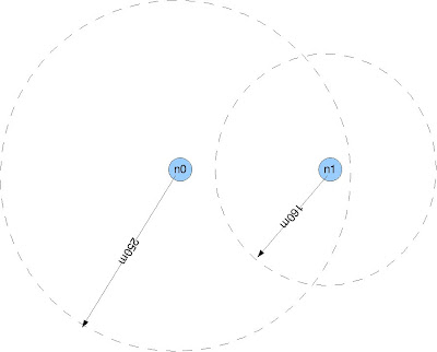


Both nodes try to send exactly one packet to the other using DSR. Because there is no bi-directional connection exist, the actual data connection could not be be established (DSR needs a bi-directional connection for route discovery). However, we can verify the difference of two transmission ranges by observing the reachability of DSR RREQ packets broadcast by each node.

The first connection starts at the 1st second, from n0 to n1. The second connection starts at the 5th second, from n1 to n0. By analyzing the trace file, I found that the all RREQ packets from n0 were not heard by n1. But all RREQ packets sent by n1 were successfully received by n0. This makes sense because n1's receiving ranges (160m) is samller than its distance to n0 (200m), thus it cannot heard any packet from n0. However, because n0's receiving range (250m) is bigger than the distance, it can hear RREQ from n1. n0 also sent out replies to n1, but n1 could not heard it.

The tcl script:
-----------------------------------


# n0 and n1 use the same transmission power.
# n0 has a receiving range of 250m, n1's receiving range is 160m.
# n0 and n1 are 200m away from each other.
# n1 cannot receive routing requests broadcast by n0;
# however, n0 can receive routing requests broadcast by n1.

# ==========================================================
#Definition
# ==========================================================
set opt(chan) Channel/WirelessChannel ;# channel type
set opt(prop) Propagation/FreeSpace ;# radio-propagation
set opt(ant) Antenna/OmniAntenna ;# Antenna type
set opt(ll) LL ;# Link layer type
set opt(ifq) CMUPriQueue ;# Interface queue
set opt(ifqlen) 100 ;# max packet in ifq
set opt(netif) Phy/WirelessPhy ;# network interface
set opt(mac) Mac/802_11 ;# MAC type
set opt(nn) 2 ;# number of mobilenodes
set opt(rp) DSR ;# routing protocol
set opt(x) 1000
set opt(y) 1000
set opt(seed) 0.0
set opt(stop) 10.0

# ==========================================================
# Initialize Global Variables
# ==========================================================
set ns [new Simulator]

$ns use-newtrace
set trace [open out.tr w]
$ns trace-all $trace

set namtrace [open out.nam w]
$ns namtrace-all-wireless $namtrace $opt(x) $opt(y)

# ==========================================================
# set up topography object
# ==========================================================
set topo [new Topography]
$topo load_flatgrid $opt(x) $opt(y)

# ==========================================================
# Create God --> General Operations Director
# ==========================================================
create-god $opt(nn)

# ==========================================================
# Create channel (koneksi wireless)
# ==========================================================
set chan_1 [new $opt(chan)]

# ==========================================================
# configure and create nodes
# ==========================================================
$ns node-config -addressType expanded \
-adhocRouting $opt(rp) \
-llType $opt(ll) \
-macType $opt(mac) \
-ifqType $opt(ifq) \
-ifqLen $opt(ifqlen) \
-antType $opt(ant) \
-propType $opt(prop) \
-phyType $opt(netif) \
-topoInstance $topo \
-agentTrace ON \
-routerTrace ON \
-macTrace OFF \
-movementTrace OFF \
-channel $chan_1


# ====================================================================
# create node 0, receiving range 250m, carrier sensing range 500m
# ====================================================================

Phy/WirelessPhy set CPThresh_ 10.0
Phy/WirelessPhy set CSThresh_ 9.21756e-11 ;#550m
Phy/WirelessPhy set RXThresh_ 4.4613e-10 ;#250m
Phy/WirelessPhy set bandwidth_ 512kb
Phy/WirelessPhy set Pt_ 0.2818
Phy/WirelessPhy set freq_ 2.4e+9
Phy/WirelessPhy set L_ 1.0
Antenna/OmniAntenna set X_ 0
Antenna/OmniAntenna set Y_ 0
Antenna/OmniAntenna set Z_ 0.25
Antenna/OmniAntenna set Gt_ 1
Antenna/OmniAntenna set Gr_ 1
set node_(0) [$ns node]
$node_(0) random-motion 0

$node_(0) set X_ 0.0
$node_(0) set Y_ 0.0
$node_(0) set Z_ 0.0

# ===================================================================
# create node 1, receiving range 160m, carrier sensing range 400m
# ===================================================================

Phy/WirelessPhy set CPThresh_ 10.0
Phy/WirelessPhy set CSThresh_ 1.74269e-10 ;#400m
Phy/WirelessPhy set RXThresh_ 1.08918e-9 ;#160m
Phy/WirelessPhy set bandwidth_ 512kb
Phy/WirelessPhy set Pt_ 0.2818
Phy/WirelessPhy set freq_ 2.4e+9
Phy/WirelessPhy set L_ 1.0
Antenna/OmniAntenna set X_ 0
Antenna/OmniAntenna set Y_ 0
Antenna/OmniAntenna set Z_ 0.25
Antenna/OmniAntenna set Gt_ 1
Antenna/OmniAntenna set Gr_ 1
set node_(1) [$ns node]
$node_(1) random-motion 0

$node_(1) set X_ 200.0
$node_(1) set Y_ 0.0
$node_(1) set Z_ 0.0


# UDP connections between from node_(0) to node_(1)

set udp_(0) [new Agent/UDP]
$ns attach-agent $node_(0) $udp_(0)
$udp_(0) set fid_ 1
set null_(0) [new Agent/Null]
$ns attach-agent $node_(1) $null_(0)
set cbr_(0) [new Application/Traffic/CBR]
$cbr_(0) set packetSize_ 512
$cbr_(0) set rate_ 200kb
$cbr_(0) set maxpkts_ 1
$cbr_(0) attach-agent $udp_(0)
$ns connect $udp_(0) $null_(0)
$ns at 1.0 "$cbr_(0) start"


set udp_(4) [new Agent/UDP]
$ns attach-agent $node_(1) $udp_(4)
$udp_(4) set fid_ 2
set null_(4) [new Agent/Null]
$ns attach-agent $node_(0) $null_(4)
set cbr_(4) [new Application/Traffic/CBR]
$cbr_(4) set packetSize_ 512
$cbr_(4) set rate_ 200kb
$cbr_(4) set maxpkts_ 1
$cbr_(4) attach-agent $udp_(4)
$ns connect $udp_(4) $null_(4)
$ns at 5.0 "$cbr_(4) start"

$ns at $opt(stop).0002 "puts \"ns EXITING...\" ; $ns halt"
$ns at $opt(stop).0001 "finish"

proc finish {} {

$ns flush-trace
close $tracefd
close $namtrace
exit 0
}


puts "Starting Simulation..."
$ns run


Powered by ScribeFire.

Thursday, January 3, 2008

Simulation involving both wired and wireless networks

NS2 document has a chapter (16.2) to describe the basice idea and indicates where to find an example (ns2/tcl/ex/wired-cum-wireless-sim.tcl). But the chapter is too brief and the example script is hard to understand.

Marc Greis gives a good tutorial at http://www.isi.edu/nsnam/ns/tutorial/.


Powered by ScribeFire.

A more discussion about RXThresh_ and CSThresh_

Tuesday, January 1, 2008

ns2 radio propagation models

ns2 radio propagation models


ns2 implements
three different propagation models to simulate the wireless channel:
the Free space model, the Two-ray ground model and the Shadowing model.

The propagation models are used to compute the received power.
When a packet is received, the propagation model determines the
attenuation between transmitter and receiver and computes the received
signal strength. If the signal strength is lower than the Carrier
Sensing Threshold, CSThresh_, the packet is discarded by the physical
layer. This threshold simulates the effect of the receiver sensibility.

If the level is higher than this threshold, the signal strength is
then compared with the receiver threshold, RxThresh_. This threshold
determines if the packet is received successfully or with errors; in
the first case the packet is passed to the MAC layer, in the second
case the packet is marked as erroneous and passed to the MAC layer that
will provide to discard it.

Erroneous packets are delivered to the MAC layer so that it can
detect a packet collision where multi-packets are received
simultaneously. In this case the MAC layer determines the ratio between
the strongest received signal strength and the sum of the other signal
levels. The ratio is then compared with the CPThresh_ threshold that determines if the packet has been destroyed by a collision or it captured the channel.

It is worth noticing that ns2
uses a threshold to determine if a packet is received correctly or not,
without considering a more correct bit error rate computation.


The Free space model is the simplest one. It assumes ideal
propagation conditions and a single line-of-sight path between the
transmitter and receiver.

The Two-ray ground reflection model considers both the direct path
and a ground reflection path. As with the free space model, both
transmitter and receiver node are assumed to be in line of sight. It
has been shown that this model is more accurate than free space model
in case of long distance line of sight path.

Both the Free space model and the Two-ray model predict the
received power as a deterministic function of the distance between the
transmitter and receiver.


A more realistic model is the Shadowing model. It adds to the
deterministic path loss, a random component to the received power that
attempts to reproduce random variability typical of wireless links
(e.g. fading). The shadowing model consists, in fact, of two parts: the
first one is the deterministic path loss that predicts the received
power from the distance between the receiver and transmitter nodes; the
second part of the shadowing model reflects the variation of the
received power at certain distance. The shadowing is simulated as a
log-normal random variable, with zero mean. The effect of shadowing
correlation is not considered.


A detailed description of the ns2 propagation models and an accurate parameter setting description can be found in the ns2 manual: http://www.isi.edu/nsnam/ns/doc/node215.html.


Moreover, it is worth to pinpoint that there exist some extensions to default ns2 propagation model that are not included into the ns2 official distribution, but can be downloaded from the ns2 contributed code web page: http://nsnam.isi.edu/nsnam/index.php/Contributed_Code.


Among several extensions the more relevant are:

• realistic channel propagation by Wu Xiuchao,

• ricean propagation model by Ratish J. Punnoose.


Original link


Powered by ScribeFire.

DSR interface queue length

It seems I cannot set the queue length in the tcl script using

node-config -ifqLen <qlen>

when I use DSR and CMUPriQueue.

The only effective way for me is to modify the C++ file dsr-priqueue.h under directory ns2/queue/. There is a statement

"#define IFQ_MAXLEN 50"

to specify the interface queue length is 50 packet, and it does changes the simulation result after I modified the value.

Is it a small bug?


Powered by ScribeFire.